square:/hda4/home/watson/PASTWORK/index.html update Thu Dec 14 04:13:49 EST 2000

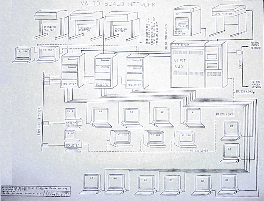
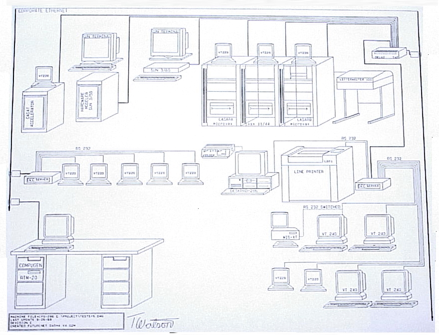
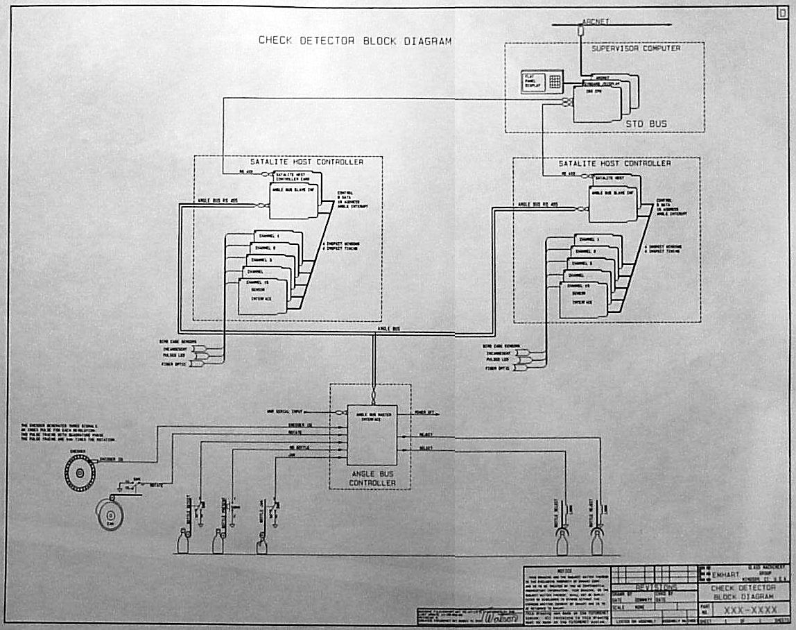
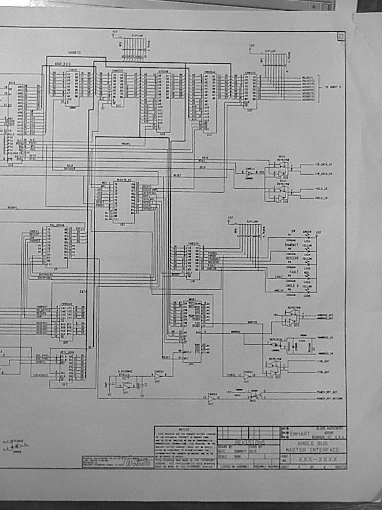
The following works were authored by Thomas A. Watson.

  • In the late eighties using networks to interconnect word processing work stations to central mini-computers was a first step in office automation. In the figure right, a process functional block diagram shows some of the first methods of moving files between a Decmate word processing system and Vax mini computers.

  • Full XGA.
    VGA 640x480
    320x240

  • In the late eighties networks of mini-computers were also used to allow design engineers to interactively design circuits and past the design to other stages of computer aided manufacturing. The figure show Valid Scald Computer Aided Engineering Workstation network.

  • Full XGA.
    VGA 640x480
    320x240

  • Also In the late eighties mini-computers were used to allow design engineers to do design verification complete functional testing or electronic designs. The functional testing could be used generate a set of digital test vectors that would be used an automatic test system to functionally test circuit boards during manufacture. The figure shows a network of mini computers used to perform functional test, the workstations and a automatic functional tester.

  • Full XGA.
    VGA 640x480
    320x240

  • In the development of a large system design normal documentation requires the creation of a complete parts database of drawings for all components, sub assemblies and assemblies. In the DOD there is also a CDRL to create a family tree of related drawings. The generation of a system wide Family tree and the maintenance of this drawing set involves hundreds to thousands of man hours of work. In 1990 Watman Associates developed a fully interactive program to create family tree drawings. The program allowed users to select drawing properties and the would create a colorized preview of drawings. When the user was satisfied with the look of the family tree DYNATREE would then create a drawing command script that when input to a Computer Aided Engineering drawing program would automatically generate the family tree drawing set. The use of DYNATREE could create the family tree drawing set for systems with thousands of drawings in a few hours.

  • DYNATREE was written in the C programing language and featured 30 plus screen with built in detail help.

    Link to view the DYNATREE screens.


  • 723x927
    VGA 640x480
    320x240

  • In the early nineties Emhart Glass Machinery decided to redesign their line of automatic glass bottle inspection equipment. The goal of the design were add more programmability to the check detection algorithms and interconnect all machines to allow for an integrated automated quality control. Mr. Watson was a principle contributor to the network system architecture shown.

  • Full XGA.
    VGA 640x480
    320x240

  • Each of the several glass inspection machines was upgraded with an embedded control computer with custom interface circuit cards to interface to physical sensors. The functional block diagram of a check detector is shown.

  • Full XGA.
    VGA 640x480
    320x240

  • The images show the schematic of a custom embedded micro-controller interface card.

  • Full XGA.
    640x480
    320x240

    Full XGA.
    640x480
    320x240


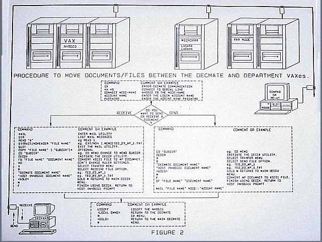
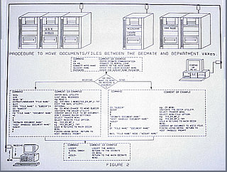
    On January 28, 1986, at 11:38, Mr. Watson was at lunch with a group of students. The students were taking a course authored by Mr. Watson on the use of Computer Aided Schematic capture and netlist database generation. In the restaurant the TV station broke to live coverage of the the launch of STS Challenger. Challenger exploded 73 seconds after takeoff. Television film footage captured the tragic explosion and its aftermath, as smoke trailed out of the craft and it fell to the ocean. All seven crew members died due to a faulty "O-ring" seal failed in the solid-fuel rocket on the shuttle's right side. Flames escaped through the failed seal. The flames burned through the shuttle's external fuel tank and a support attaching the rocket to the tank. The rocket broke loose and pierced the tank. Liquid hydrogen and liquid oxygen fuels ignited, tearing the shuttle apart. The shuttle launch program was not resumed until designers made modifications and National Aeronautics and Space Administration (NASA) management implemented stricter regulations regarding quality control and safety. The accident and the ensuing investigation into its cause temporarily halted the space shuttle program. Shuttle missions resumed on September 28, 1988, with the flight of the shuttle Discovery.

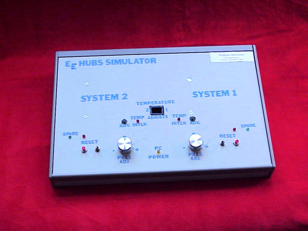
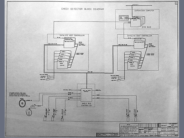
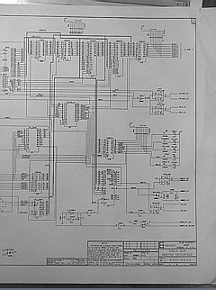
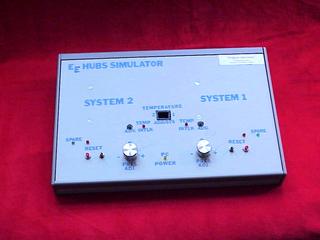
    In 1990, as a result Challenger accident NASA contracted with the PowerDyne Division of Raymond Engineering for the development the Hydraulic Ultra Sonic Bolting System. Mr. Watson as a Consultant to Raymond Engineering designed and developed the HUBS control program. The HUBS program was a real time embedded control program for the controlled sequential bolting of the joints of the solid rocket boosters. The program maintained a database of the bolting process and provided complete calibration of pressure and ultrasonic load measuring instrumentation. To provide realtime signal emulation Mr Watson designed and fabricated the HUBS Electronic Emulation Simulator.

    For an excellent discussion of Space Shuttle Challenger disaster


  • Full XGA.
    VGA 640x480
    320x240


    While working at Northrup Grumman Norden Systems Mr. Watson developed several programs to extract time aligned 4 channel IQ, IMU and calibration data sets. The extracted data sets were used to create SAR, Wide Area SAR, Ultra high resolution (UHR) SAR and IFSAR maps. The APG-76 RADAR has 4 receiving antenna and this allows for mapping with simultaneous detection and display of moving targets.

  • The image shows the amplitude of raw radar data. The Y dimension is radar range and the X dimension is time. Today radars generate several thousand pulse a second and by looking or pulsing for several seconds several hundred megabytes of complex radar data is collected and processed into photo looking images. UHR images often are created with more than a gigabyte of raw IQ RADAR data.

  • Full XGA.
    VGA 640x480
    320x240

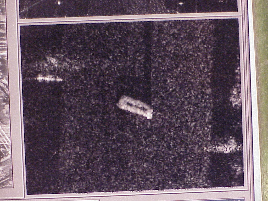
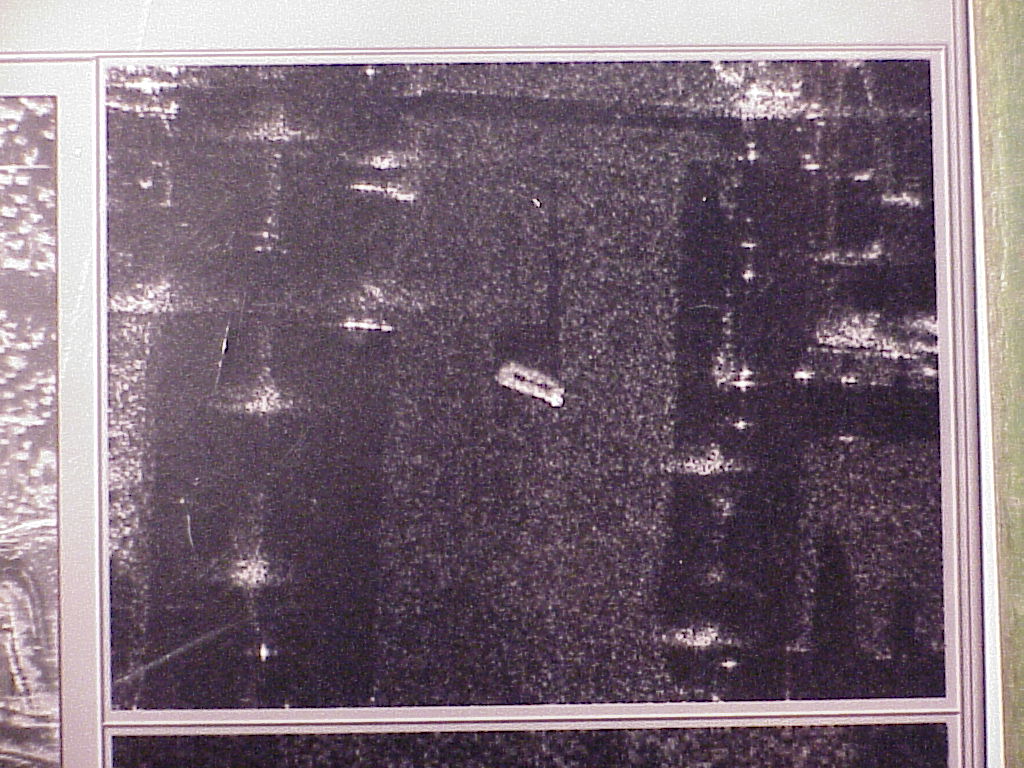
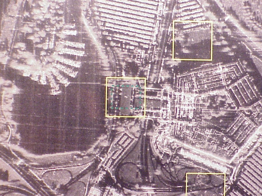
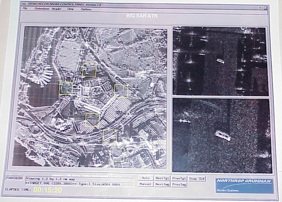
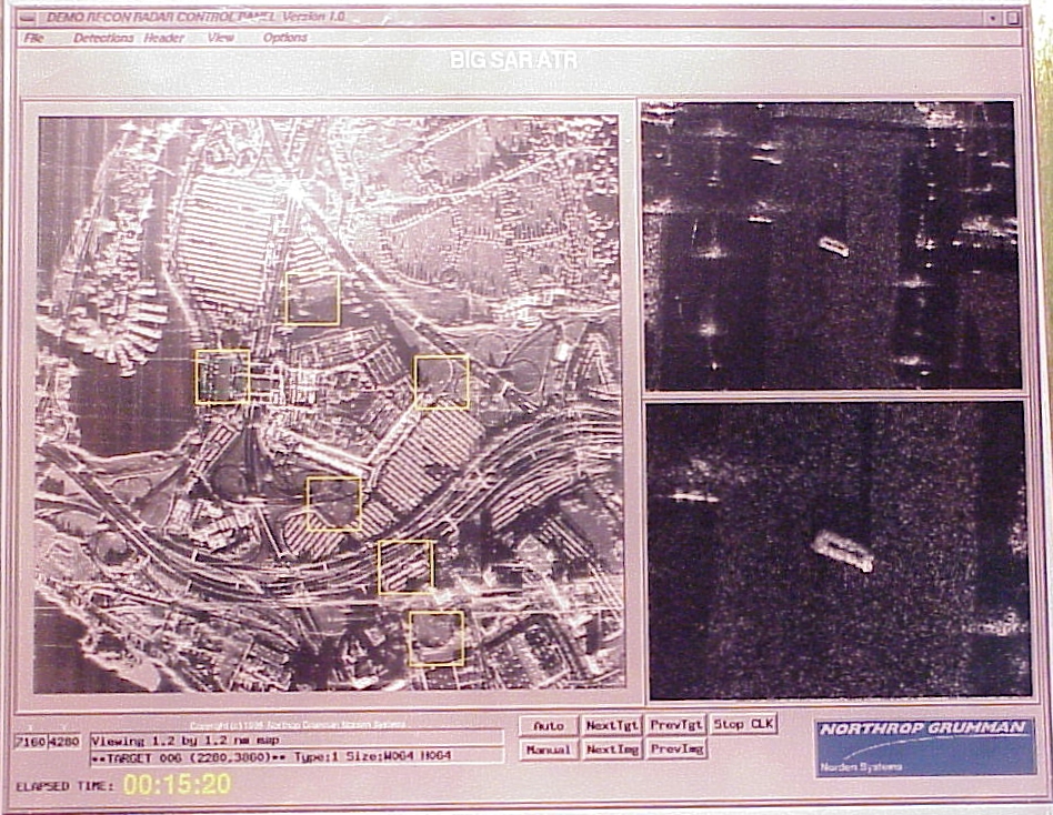
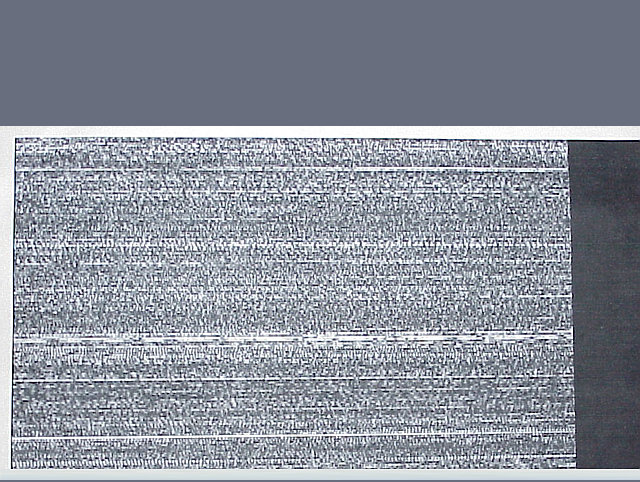
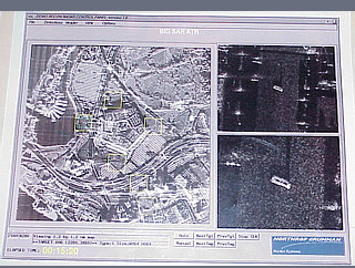
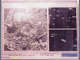
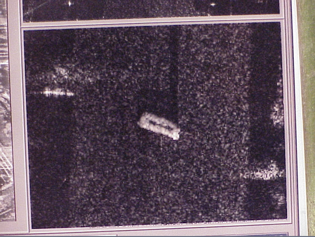
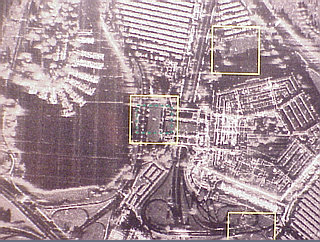
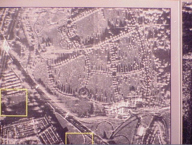
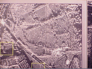
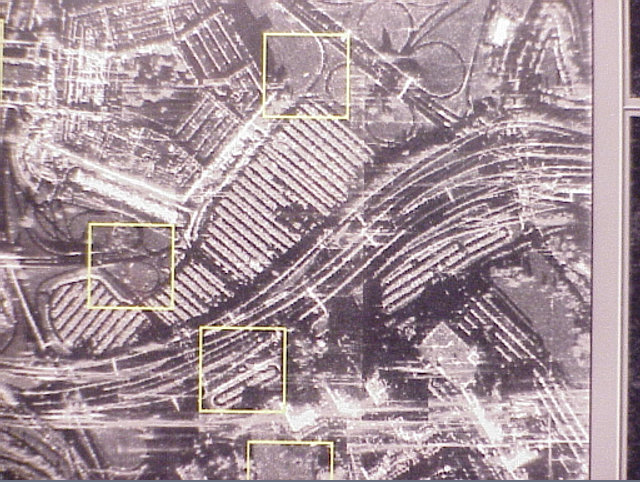
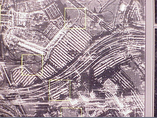
    The F-111 Upgrade Options page show the APG-76 radar and images showing Moving Target Indicators(MTI).
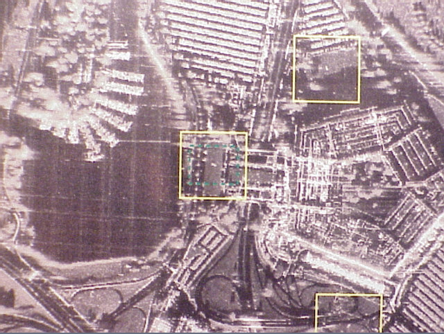
    The GPS Guided Weapons Page also features APG-76 Ultra High Resolution images.

  • Interferometric synthetic aperture radar (IFSAR) data can be used in the generation of rectified SAR images co-registered with an accurate terrain elevation file. The use of a wide area IFSAR map can also be married with a trajectory of observation with a fixed or moving observation view. The image shows a snapshot of a perspective view.
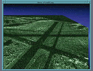
    Additional IFSAR views and a 10.3 meg. flyby movie

  • 660x517
    320x240


  • To demonstrate a new and more efficient way of evaluating large area high resolution radar imagery an Xwindow based display demonstration was created. The application was developed and compiled on a common Intel based PC using the Linux operating system. This demonstration software was also compiled to run on SGI irix and Sun Solaris and HP hp-ux systems. The images show a radar display demonstration program that incorporated the functionality of automatic target recognition. A target is located within a familiar pentagon area. The detection of likely target signature was highlited with squares. A radar operator could quickly look at zoomed area of detected possible targets.

  • Full XGA.
    VGA 640x480
    320x240

    Full XGA.
    VGA 640x480
    320x240

  • These two images show two levels of zoom of a selected target area.

  • Full XGA.
    VGA 640x480
    320x240

    Full XGA.
    VGA 640x480
    320x240

  • This image shows the current selected zoom area shown in detail above.

  • Full XGA.
    VGA 640x480
    320x240

  • These two images are enlarged photos of the wide area map to show the level of detail in the map.

  • Full XGA.
    VGA 640x480
    320x240

    Full XGA.
    VGA 640x480
    320x240